")
")
")
")


This section concerns important information about the LPG tanks, their production process and the necessary equipment. If you are interested in supplying LPG tanks, see the LPG Storage Tanks of ANDRIANOS here.
The LPG storage tank is a stable metal pressure vessel, for gas storage, with more than 150 liters, cylindrical or spherical, which meets the requirements of the Pressure Equipment Directive 97/23 /EC.
LPG tanks are divided into Above ground (external) and Underground. The Underground tanks are buried to ground and covered with soil. The advantage of underground tanks is the increased fire protection, while the basic advantage of above ground tanks is the economic installation.
LPG Tank Equipment: The gas tank according to the legislation must be equipped with: Filling valve, Gaseous Phase Valve, Safety Gauge, Layout Indication Level, Pressure Relief Safety Valve, Max Level Limiter/Indicator & Fluid Relief Valve.
Certificate of Manufacture: Each LPG tank must be issued with a Certificate of Manufacture in which it is listed: the Manufacturer, the Year of Manufacture, the Serial Number, the Materials used for construction, the Regulation or Standard and Compliance with Directive 97/23/EC, the Tests it has undergone & its Capacity.
.png)
Indicative Diagram of Components on Above Ground tanks
*Underground tanks do not drain from the bottom of the tank.
LPG Tank Equipment:
The tank, whether is underground or above ground, is supplied with the following accessories:
Group of dispensing service:
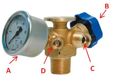
This service group allows the delivery of the LPG plant to which it is connected, as well as to respond to different needs for the operating and safety features. This equipment is:
- (A)The pressure gauge for controlling the internal gas pressure in the tank. It has a scale of 0 to 25 bar, with the red mark of 17.65 bar corresponding to the maximum operating pressure.
- (B) (C) It' s also present a shut-off valve in the sampling line to interrupt the supply of gas in case of anomalies or gas inactivity.
- (D) Lastly there is a flow excess valve that interrupts the flow in case the pressure is too high (as in the case of rupture of the intake pipeline).
Filling valve
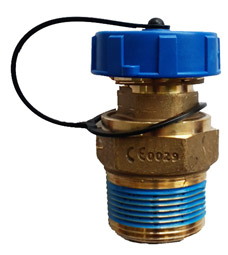
This valve is installed in order to allow the supply of LPG. It's equipped by a shutter to ensure the closure of the valve, which opens automatically with the pressure in the process of refueling.
Liquid phase gas with drawal

This valve is used exclusively by specialized personnel. It is connected via a dip tube to the bottom of the tank to withdraw the gas directly into the liquid phase.
Safety valve with under valve

This valve is a spring-type "safety valve", which has the purpose of ensuring that inside the tank there is never a pressure higher than 17,65bar. In case of higher pressures the valve makes the gas escape until the pressure lower than 17.65bar. The calibration of the valve is ensured by the good preservation of the same to load the user (who must ensure, in particular, also the presence of the protective cap) and by replacing every 2 years.
Level indicator

This indicator provides the percentage of LPG in the liquid phase present in the tank showing the total quantity of product present. The tank should also refuel as soon as the indicator reaches 20% of the fill.
Name plate

Is a plate bearing, indelibly in the event of fire, the identification data of the tank, its manufacturer, the CE marking and the notified body that issued it. The label construction material is indelible so that the marking is not destroyed in the event of a fire.
In addition to the label of the tank there should be an information plate of the product stored in the tank, which will indicate the word "LIQUID" or "PROPANIO" respectively, a ban on smoke and the use of flame and finally a billboard listing the telephones need of the reservoir reservoir, the tank owner and the Fire Brigade.
Plastic Cover

Thanks to the innovative materials used in the production and manufacture, and attractive design, these covers are perfect for horizontal and vertical tanks with a diameter of 800, 1000 and 1200 mm, thus covering the range of capacities ranging from 200 up to 5000 lt.
Features:
- Cover: PolyPropylene HD
- Body: PolyPropylene HD
- Dimensions: 95x56x40 (H); 60x32 (V)
- Complete with Box for Cathodic Protection (if required)
Contact ANDRIANOS for more information about LPG Tanks
Factory Reconstruction Process – Factory Refurbished
A common procedure in the LPG industry is the reconstruction of used LPG tanks and then re-certification according to technical regulations. Below are the stages of processing the tanks during the factory reconstruction.
Phase 1st: Cleaning

Incoming refueling tanks are placed in a special area of the plant at the factory so that they can proceed with the decompression and dismantling of all components and then be picked up and transferred to the next processing stages.
Phase 2nd: Hydraulic Testing

Each tank is initially subjected to a hydraulic test at 25.24 bar. The pressure is kept constant in the tank, taking care of its welds, especially the bottom one.
Phase 3rd: Sandblasting
During the sandblasting process, the degree of sand ejection and the surface roughness are critical for the subsequent proper adhesion of the epoxy coating to the metal substrate of the tank. According to ISO 8501-1, the tank must have a specific degree of sanding, determined by law. The adhesion of the coating is one of the final quality checks performed in the tank. Appropriate adhesion of the epoxy coating is a prerequisite for the epoxy coating to provide a sufficient guarantee of durability in underground installation conditions.
Phase 4th: Tank Coating Thickness Tests

Prior to looking at the thickness of the coating, the operator holding the second level of UNI EN ISO 9712 performs a careful visual examination of both the outside and the interior of the tank to assess the possibility of proceeding reconstruction in the next stages. When no noticeable defect is found, an ultrasound examination is performed with a 150x150 mm knit pattern, controlling the thickness to meet the specifications of the appropriate certificate as determined by the applicable standards.
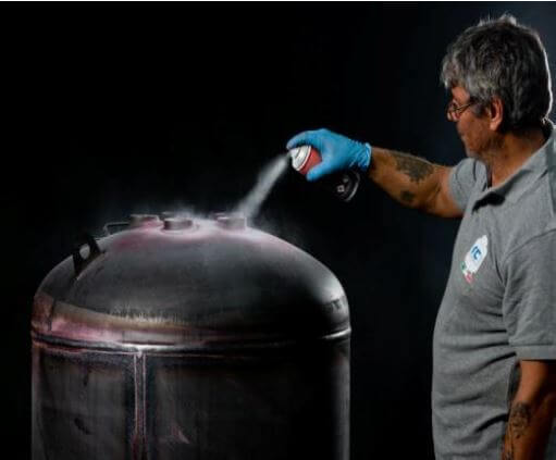
Phase 5th: Painting

In order to avoid oxidation problems and after thorough cleaning and removal of dust residues, the tank is transferred to the spray chamber for the application of two-component (bottom tanks) or two-component epoxy resin (underground tanks) through a mixer unit preheating the components which will be used at 60 ° C. The operator must maintain the uniformity of coating thickness in each tank, at least 120 μm for heights or 500 μm for underground. If the test has a positive result, then the tank is transferred to its subsequent processing steps.
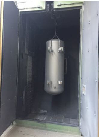
Phase 6th: Drying Furnace

Completing the dyeing step, the treatment cycle involves placing the tank in an oven where it remains for about 60 minutes at a temperature of 90 ° C. Passing the tank from an oven has two reasons:
- Curing the paint to allow subsequent treatment of the tank without the risk of damage to the coating.
- Allows evaporation of the water strip created on the inner walls of the tank.
Phase 7th: Final Tests

In the next step, the necessary checks are carried out with certified and calibrated measuring instruments as prescribed by law. In order to communicate the results of these controls, the tanks must comply strictly with the provisions of Circular P2004.
Phase 8th: Assembling parts
Upon exiting the oven, the necessary tank safety instruments are assembled to perform under pressure tests as well as tightness tests. The tank pressure test is performed at 7 bar with sufficiently dry air to avoid condensation of moisture in the air inside the tank.
The tanks then come out of the production chain support chains and the final brand-new valves and fittings are placed.
Production Process of new tanks
Phase 1st: Preparation and Assembly οf Funds-Plating

The bottom of the tanks is received in perforated structure and welded by certified welders. The sheets are welded with an automated welding machine with double longitudinal welding, both internal and external. The resultant structure is inspected visually.
The two bottoms, perforated or blind, are assembled together to the plating. The so resulting tank, although still raw, is visually checked to establish the proper cohesion of the parts, to be able to give way to the circular weld which closes perfectly the tank.
Phase 2nd: Examination Penetrating Fluids & Radiographic Examination
All weldings, both longitudinal and circular, are controlled to exclude potential "seamless" areas by penetrating fluid testing as described in UNI EN ISO 12542: 2010 by a CICPND, 2nd level technician.
Weldings are tested by sampling, even by X-ray examination at 10% of their total length, as required by UNI EN ISO 12542: 2010, from the 3rd CICPND level.
Phase 3rd: Finishing

All tanks controlled in all the above stages and finally approved for production proceed to the welding of the base, rings and well.
The next steps in the construction of a new tank are exactly the same as those of the factory rebuilding of the tanks:
Hydraulic Testing
Sandblasting
Tank Coating Thickness Tests
Painting
Drying Furnace
Final Tests
Assembling parts


